1. Introduzione
The PeakTech 3432 is a versatile electrical testing device designed for efficient and safe detection of fuses and circuits. It comprises a transmitter and a receiver unit. The transmitter acts as a signal generator and a socket tester, while the receiver is used to locate fuses within a fuse box. Additionally, the receiver features a Non-Contact Voltage (NCV) detector for identifying live voltage without direct contact. The transmitter also allows for RCD (Residual Current Device) testing by simulating a fault current.
2. Istruzzioni di sicurità
Please read this manual thoroughly before operating the device. Adhere to all safety warnings and operating instructions to prevent injury or damage to the device. This device is rated CAT III 250V and is suitable for 230V 50/60Hz systems. Always ensure the power supply is disconnected before working on electrical installations, unless specifically instructed otherwise for testing purposes.
- Always wear appropriate personal protective equipment (PPE) when working with electricity.
- Ùn aduprate micca u dispusitivu s'ellu pare dannighjatu o ùn funziona micca currettamente.
- Ùn supere micca u volu specificatutage valutazioni.
- Ensure the battery is correctly installed and replaced when low.
- The device is designed for indoor use and has an IP40 rating, meaning it is protected against solid objects larger than 1mm but not against water.
3. Cuntenutu di u pacchettu
Verificate chì tutti l'articuli sò presenti in u pacchettu:
- 1 x PeakTech 3432 Receiver
- 1 x PeakTech 3432 Transmitter with connection cable and plug
- 1 x 9V Block Battery
- 1 x User Manual (German/English)
- 1 x Borsa di trasportu

Image: All components included in the PeakTech 3432 package: the blue receiver, the black transmitter with its plug, a 9V battery, the user manual, and a black carrying bag.
4. Produttu Finituview
The PeakTech 3432 consists of two main units: the Receiver and the Transmitter. Familiarize yourself with their components and controls.

Image: Detailed diagram illustrating the various parts of the PeakTech 3432 Receiver and Transmitter, including buttons, indicators, and battery compartment.
Cumponenti di u ricevitore:
- NCV Signal Indicator
- NCV Test Unit
- Measurement Unit Housing
- Battery Compartment (for 9V Block battery)
- NCV Button (for non-contact voltage test)
- On/Off Button / Reset Button
Cumponenti di u trasmettitore:
- Connection Cable with Plug
- Test Button for RCD Test
- LED for RCD Test
- LED Indicator for Plug Polarity
5. Setup
5.1 Installazione di batterie
- Locate the battery compartment on the back of the receiver unit (Component 4 in Product Overview).
- Aprite a tappa di u compartimentu di a batteria.
- Insert a 9V block battery, ensuring correct polarity (+/-).
- Chiudere in modu sicuru u coperchiu di u compartimentu di a batteria.
5.2 Verificazione iniziale
Before use, briefly press the On/Off button on the receiver to ensure it powers on. The NCV signal indicator should briefly light up, confirming battery power.
6. Operating Instructions
6.1 Fuse Detection
This function helps identify which fuse controls a specific electrical circuit.
- Plug the transmitter into a live socket on the circuit you wish to identify.
- Go to the fuse box.
- Turn on the receiver by pressing the On/Off button.
- Slowly scan the fuses in the fuse box with the tip of the receiver.
- The receiver's NCV signal indicator will light up verde when no signal from the transmitter is detected, indicating it's not the correct fuse.
- The receiver's NCV signal indicator will light up rossu and emit an audible signal when the signal from the transmitter is found, indicating you have located the correct fuse for that circuit.
- Once the fuse is identified, you can safely switch it off for maintenance or repair.

Image: The receiver unit held near a fuse in a fuse box, displaying a green light, which signifies that the signal from the transmitter has not been found on this particular fuse.

Image: The receiver unit held near a fuse in a fuse box, displaying a red light, which signifies that the signal from the transmitter has been successfully detected on this fuse.
6.2 Non-Contact Voltage (NCV) Detection
The receiver can also be used independently for non-contact voltage dittizzioni.
- Accende u ricettore.
- Press the NCV button (Component 5).
- Hold the tip of the receiver near a conductor, cable, or socket.
- Sè live AC voltage is detected, the NCV signal indicator will light up red and an audible signal will sound. The intensity of the signal (both visual and audible) may increase with proximity to the voltage fonte.
6.3 Socket Testing
The transmitter unit doubles as a socket tester, indicating the wiring status of a 230V Schuko socket.
- Plug the transmitter into the socket you wish to test.
- Observe the LED indicators on the transmitter (Component 4). These LEDs will illuminate in specific patterns to indicate the wiring status (e.g., correct wiring, missing ground, phase/neutral reversal). Refer to the legend on the transmitter for specific indications.
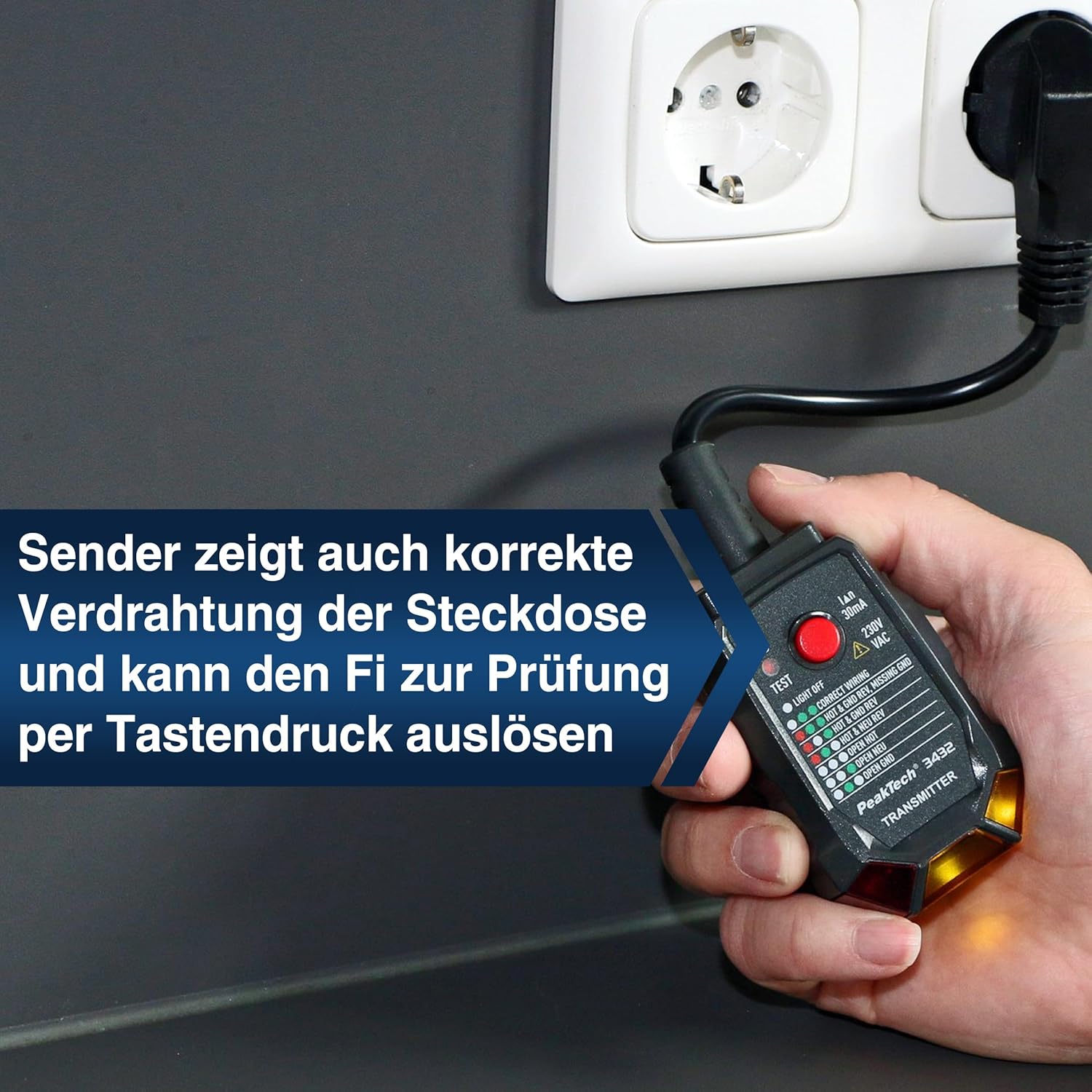
Image: The transmitter unit is plugged into a standard wall socket. Its LED indicators are visible, providing feedback on the socket's wiring configuration and allowing for RCD testing.
6.4 RCD Testing
The transmitter can test the functionality of a 30mA RCD (Residual Current Device).
- Ensure the transmitter is plugged into a live socket.
- Press the RCD Test button (Component 2) on the transmitter.
- If the RCD is functioning correctly, it should trip (switch off) within a short period.
- If the RCD does not trip, it may be faulty and should be inspected by a qualified electrician.
- Reset the RCD after testing.
7. Mantenimentu
7.1 Pulizia
Wipe the device with a dry, soft cloth. Do not use abrasive cleaners or solvents. Ensure the device is dry before storage or use.
7.2 Sustituzione di batterie
When the receiver's battery is low, the signal indicators may become dim or the device may not power on. Replace the 9V block battery as described in Section 5.1. Dispose of used batteries according to local regulations.
7.3 Storage
Store the device in its carrying bag in a cool, dry place, away from direct sunlight and extreme temperatures. If storing for extended periods, remove the battery to prevent leakage.
8. Risoluzione di prublemi
- L'apparechju ùn s'accende micca: Check if the battery is correctly installed and fully charged. Replace the battery if necessary.
- No signal detected during fuse finding: Ensure the transmitter is plugged into a live socket on the circuit you are testing. Verify the socket is functional using the transmitter's socket test feature.
- Multiple fuses show a signal: In some installations, due to proximity or wiring configurations, the receiver might pick up a signal from adjacent fuses. To pinpoint the exact fuse, try scanning more slowly and observing the strongest signal indication (brightest light/loudest sound). It's important to note that this device works with live voltage, and signals can sometimes bleed to nearby conductors.
- RCD does not trip during testing: Ensure the transmitter is correctly plugged into a live socket. If the RCD still does not trip, the RCD itself may be faulty and requires inspection by a qualified electrician.
- Inaccurate NCV readings: Ensure there are no strong electromagnetic fields nearby that could interfere with the NCV detection.
9. Specificazioni
| Feature | Specificazione |
|---|---|
| Numero di mudellu | P 3432 |
| U fabricatore | PeakTech |
| Dimensioni (L x W x H) | 18.9 x 4.9 x 3.4 cm |
| Pesu | 254 grammi |
| Fonte d'energia | Battery Powered (9V Block) |
| Vol. Operativu Minimutage | 230 Volts |
| Frequency | 50/60 Hz |
| Specificazioni di sicurità | CAT III 250 V, IP40 |
| Temperatura nominale superiore | 50 gradi Celsius |
| Tipu di misurazione | Fuse Detector / Circuit Detector |
10. Garanzia è Support
10.1 Garanzia
The PeakTech 3432 comes with a 3-year availability for spare parts. For specific warranty terms and conditions, please refer to the documentation provided with your purchase or contact PeakTech customer service.
10.2 Assistenza Clienti
For technical assistance, troubleshooting beyond this manual, or warranty claims, please contact PeakTech customer support. Contact information can typically be found on the manufacturer's websitu o in l'imballu di u produttu.